With this article you will have the answer to your How to read electrical plan pdf? question. Indeed TEXT tutorials is even easier if you have access to content and different articles as well as different answers to questions. Our CAD-Elearning.com site contains all the articles that will help you to progress in the study of this wonderful universe of Home Design. Browse our site and you will find different articles answering your different questions.
And here is the answer to your How to read electrical plan pdf? question, read on.
Introduction
People ask also, what are the 7 parts of electrical plan?
- (A) Location and Site Plans.
- (B) Legend or Symbols. Refer to Appendix A – Electrical Symbols.
- (C) General Notes and/or Specifications.
- (D) Electrical Layout.
- E) Schedule of Loads. Schedule of load in tabulated form shall indicate:
In this regard, what is the first step in reading electrical wiring plan? One of the first steps in reading an electrical schematic is understanding the different symbols used to represent system components, or at least having access to a schematic symbol cheat sheet.
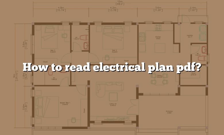
Considering this, what is shown on a building electrical plan? Electrical plans must show all interior and exterior walls, stairs, and large devices, such as furnaces, water heaters, etc., that require power. Built-in fixtures and cabinetry, such as in bathrooms and kitchens, should also be drawn to better locate the electrical outlets and other devices.
As many you asked, what are the parts of electrical plan? The major parts of an electrical plan include general and specialized electrical re- quirements, lighting systems, and the electrical distribution system. Every electrical plan must be designed to recognized industry standards, use ap- propriate electrical symbols, and conform to all applicable codes.
How do you read one line drawing?
A one line typically starts at the top of the page and works its way down. It will start with the utility or other means of incoming power and its disconnecting device. It will then flow down to the distribution equipment like a switchboard or MCC and then finally it will end with the loads, like a motor or panelboard.
What is load schedule?
The load schedules is a summary of the data that helps electrical installers to know the equipment ratings and their contribution to the overall power consumption in an installation. The data in the load schedules is usually backed by the calculations which are based on standard electrical codes.
What is electrical diagram and symbols?
Basic electrical and electronic graphical symbols called Schematic Symbols are commonly used within circuit diagrams, schematics and computer aided drawing packages to identify the position of individual components and elements within a circuit.
What are the three types of electrical diagrams?
Types of Electrical Diagrams or Schematics They are wiring, schematic, and pictorial diagrams.
Why do we need to interpret the electrical wiring plan?
It shows the components of the circuit as simplified shapes, and how to make the connections between the devices. A wiring diagram usually gives more information about the relative position and arrangement of devices and terminals on the devices.
What is electrical design analysis?
Electrical design analysis is primarily about detailed calculations of wire gauges, conduit sizes, protective device ratings, fault currents, voltage drops and other technical matters necessary for the safe and proper operation of electrical systems.
How do you read an electrical SLD diagram?
When interpreting a single line diagram, you should always start at the top where the highest voltage is and work your way down to the lowest voltage. This helps to keep the voltages and their paths straight. To explain this easier, we have divided the single line into three sections.
What are the electrical wiring diagram?
A wiring diagram is a simple visual representation of the physical connections and physical layout of an electrical system or circuit. It shows how the electrical wires are interconnected and can also show where fixtures and components may be connected to the system.
What is schematic diagram in electrical?
A schematic diagram is a fundamental two-dimensional circuit representation showing the functionality and connectivity between different electrical components. It is vital for a PCB designer to get familiarized with the schematic symbols that represent the components on a schematic diagram.
How do I calculate load?
Multiply the mass of the object by the gravitational acceleration of the earth (9.8 m/sec2), and the height in meters. This equation is the object at rest’s potential energy. Potential energy is measured in joules; this is the load force.
How do you read a load schedule?
How do you calculate amp load?
To calculate amperage, use the equation Amps = Watts/Volts. For example, a 200W light bulb on a 120V circuit would draw about 1.67 amps. Calculate the TOTAL amperage rating of all devices. Make sure they DO NOT exceed 80% of the breaker’s total amperage.
What are the 5 electrical symbols?
There are five commonly used symbols in Electrical – Switch, Wire, Contactor, Motor, Transformer. These symbols can be used in any electrical drawings. Switches are used for ON/OFF any control circuit.
What are the 6 most common symbols used for an electrical schematic diagram?
- Battery. The symbol for a battery is shown below.
- Resistor. The schematic symbol of the resistor are drawn in two different ways.
- Potentiometer.
- Schematic Symbols of a Transistor.
- Integrated Circuit.
- Logic Gates.
- Inductor.
- Transformer.
How do I calculate current?
The current formula is given as I = V/R. The SI unit of current is Ampere (Amp).
Wrapping Up:
I hope this article has explained everything you need to know about How to read electrical plan pdf?. If you have any other questions about TEXT software, please take the time to search our CAD-Elearning.com site, you will find several TEXT tutorials. Otherwise, don’t hesitate to tell me in the comments below or through the contact page.
The following points are being clarified by the article:
- How do you read one line drawing?
- What is load schedule?
- What is electrical diagram and symbols?
- Why do we need to interpret the electrical wiring plan?
- What is electrical design analysis?
- How do you read an electrical SLD diagram?
- What is schematic diagram in electrical?
- How do I calculate load?
- What are the 5 electrical symbols?
- What are the 6 most common symbols used for an electrical schematic diagram?